Radiated Immunity test is one of the EMC tests. The purpose of performing this test is to see whether the equipment under test (EUT) can work properly when there is an electrical field. Electrical fields could be created by cell phones, motors, some intentional radiators, and RF noise. The radiated immunity tests are generally performed according to IEC 61000-4-3 standard.
In this test, a frequency scan is performed at fixed levels of field strengths. The test has a series of frequency steps. Each frequency step corresponds to a percentage of current frequency.
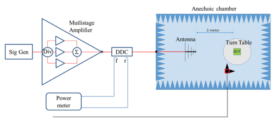
Radiated immunity field is created in the lab by a signal generator. The test lab calibrates the field around the environment where the product is placed. The signal generator creates a modulated sinusoid. Then this sinusoid is fed to a broadband RF Power Amplifier. Then this signal is given to the transducer ( the antenna ).
At each step of the test, the frequency is fixed at a level and the field strength is brought to a specified value. These conditions are kept for a dwelling time and the product is observed. The product is observed for an unintended behavior. Typical value for electric field strength is 3V/m for domestic products and 10V/m for industrial products. The strength of E-field applied during the test can change according to the product standard. If the tested product is a military purpose, the field can go up to 200 V/m.
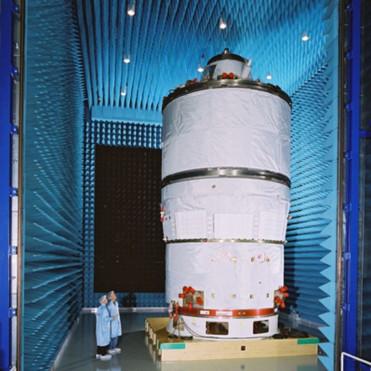
Higher Field strengths should be used for some other products. These might be automotive and medical products. The field applied is very intense greater than 10V/m. Therefore, it may harm people around. This is why the test should be conducted in a closed environment where there is little transmission of fields to outside. The tests are performed in anechoic chambers. As understood from the name, the room where the test is performed absorbs the field generated inside. The field inside is absorbed in order to prevent the reflected wave to interfere with the one sent from antenna (or the device in emission tests).
The main equipments that have to be used in the test are as follows:
- Antenna
- Field Probe
- Power Amplifier
- Signal Generator
- Control software and a computer
- Anechoic Chamber
Some common failures during the Radiated Immunity test is listed below:
The field may induce voltage on signals. The PCB under test might be affected.
- Wireless Interference
- The product’s demodulating the generated signal
- Logic error, when the eye diagram is small, or almost closed
- Measurement error
- Other performance losses
References:
Wikipedia. 2018. EMC Radiated Immunity. [ONLINE] Available at: https://en.wikipedia.org/wiki/Electromagnetic_compatibility. [Accessed 13 July 2018].
emcfastpass. 2017. The beginner’s guide. [ONLINE] Available at: https://emcfastpass.com/emc-testing-beginners-guide/emc-immunity-testing/. [Accessed 13 July 2018].
Laplaceco. 2017. RF Immunity. [ONLINE] Available at: https://www.laplace.co.uk/iec61000-4-3/. [Accessed 13 July 2018].
Prepared by: Eren Berk KAMA, Electrical-Electronics Eng. (BSc)
Edited by: Yusuf Ulas KABUKCU, Electrical-Electronics Eng. (BSc)


 Global EMC